RCS03 combines the vertical motion of the 2 probe antennas and the rotary motion of the sample to perform near-field measurement in a spiral shape, then converts the result into far-field.
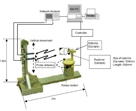
• Its spiral scanning capability enables whole-circumferential RCS measurement of the sample.
• Substantial analysis and display items.
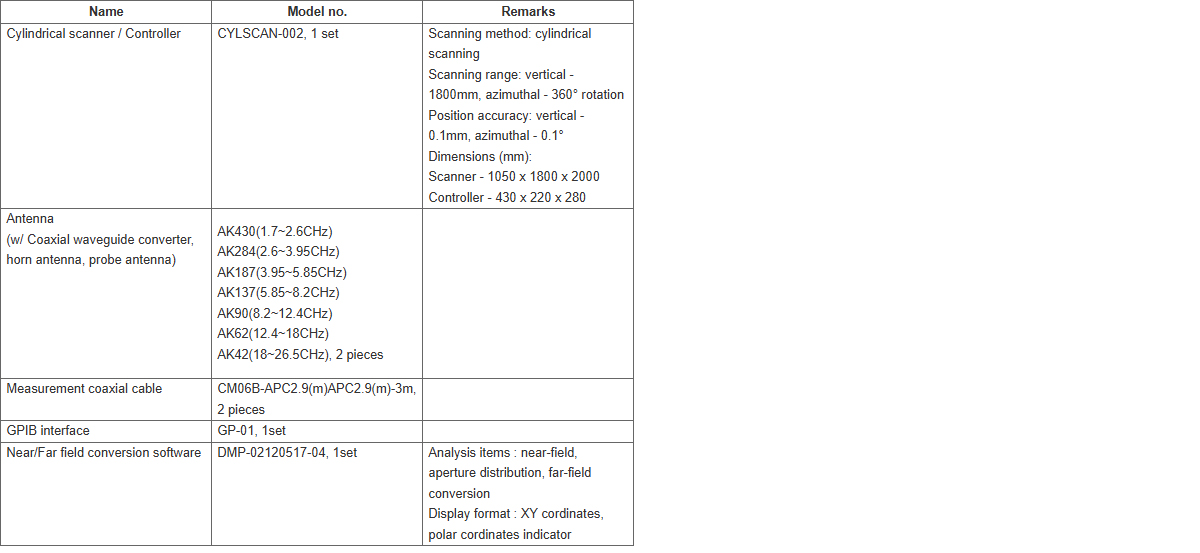
Required : Vector network analyzer, Windows PC (memory 1GB and above, CPU Pentium4 3.0GHz or above, OS Mmicrosoft Windows XP SP3 or later)
When the scattering pattern of radar cross section (RCS) is measured, the characteristic is usually evaluated in the far-field area.
In that case it is measured in the radio anechoic chamber to reduce unnecessary reflected wave and likely to deviate from the condition of the far-field according to the size or the measuring frequency.
Shown here is a cylindrical scanning surface which is extended from an improved image-based circular near-field to far-field transformation (NF-FFT) developed for smaller measurement facilities and for large targets with pronounced scattering centers offset from the center of the imaging area.
Scanning over a surface instead of a circle permits RCS estimations for targets whose size in the direction perpendicular to the measurement plane is comparable to their extension in the measurement plane.
The approach consists in near-field imaging of the target, followed by integration of the image. The focusing operator, which is used to generate the image, is built in such a way so that the image of an electrically small PEC sphere is exactly the delta function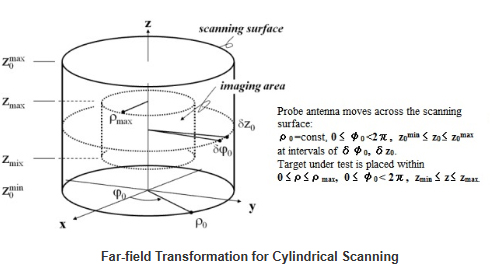
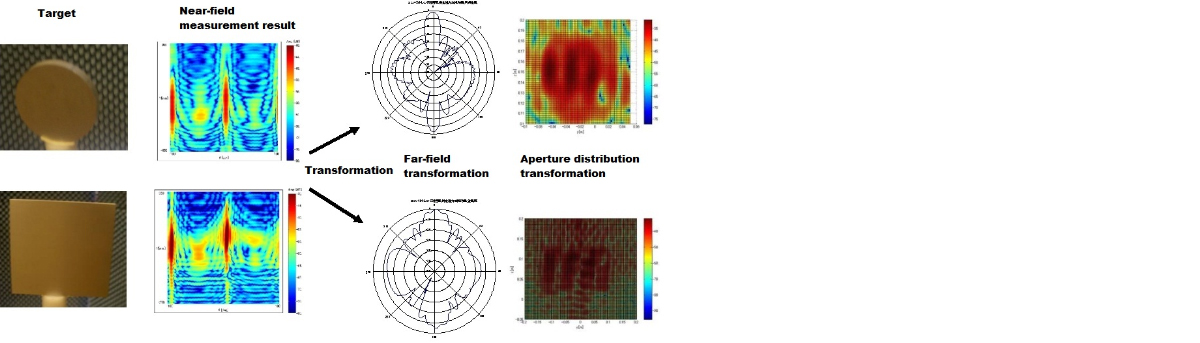
Images below indicate reflectance from two small conductor balls with different radii.
The image on the left shows the internal distribution at frequency step of δf=200MHz, azimuth step of δφ0=18°,and z=0.
The image on the right shows the internal distribution at frequency step of δf=50MHz, azimuth step of δφ0=3°.
The image on the left indicates the values of Ψ(x, y) with top 35% cut off..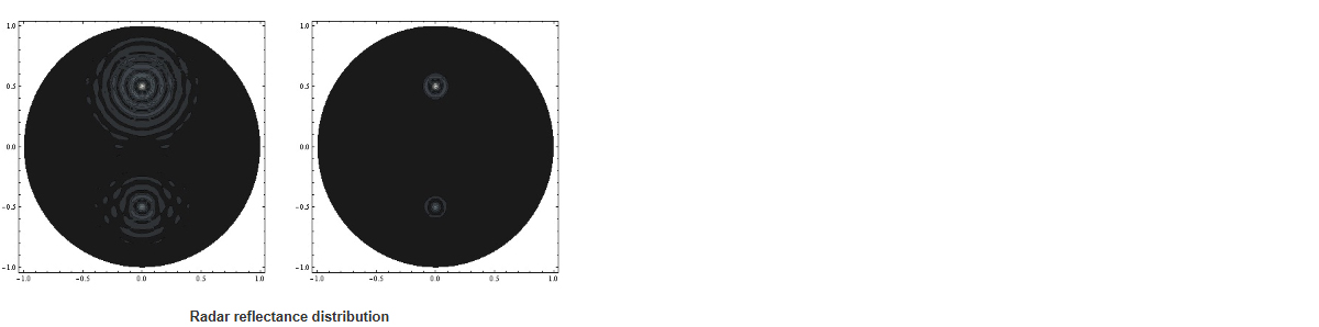
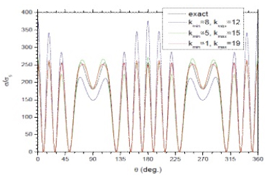
Comparison between the result arose from the difference in the sampling rate δε and the theoretical exact solution, when conductor balls are placed in the horizontal plane.
Far-field RCS transformation of two small conductor balls with different radii