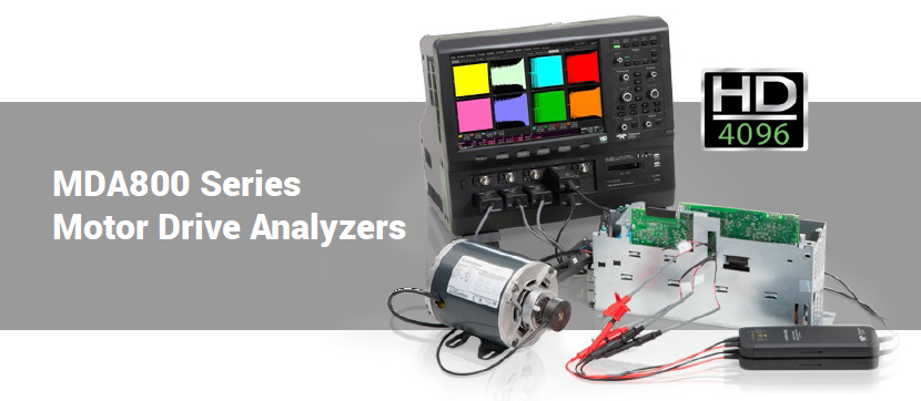
| MDA800 Motor Drive Analyzers |
| MDA8000 S eries Moter Drive Analyzers |
| |
 |
| |
| Key Features |
• Complete Motor Drive System
• Debug and Validation in
• One Instrument
• Three-Phase Power Measurements;
• Real, Apparent, Reactive Power
• Efficiency Measurements
• User-Configurable Power Table
• Two- and Three-Wattmeter Methods
• Supported
• Per-Cycle Time-Correlated
• Waveforms From Power Values
• Dynamic Drive Response Analysis,
• From Startup To Overload
• Unique Zoom+Gate Mode
• Line-Line To Line-Neutral Voltage
• Conversion
• 1000 VRMS Isolation with
• HVD Series Differential Probes
• Easily Interface Other
• Current Measurement Devices
• Complete Motor Integration
• (Torque, Speed, Position)
• Flexible Setup Capability
• Graphical User Interface |
|
Motor Drive Analyzers provide complete three-phase power analysis from motor drive input through motor mechanical output, with results in a convenient Numeric table format. Motor speed, position,
and torque integration are the most complete available. Long memory, per-cycle “synthesized” Waveforms and Zoom+Gate mode provide powerful dynamic drive and motor analysis. 8 analog input channels (MSO optional) with high resolution (12-bits), sample rate (up to 2.5 GS/s), bandwidth
(up to 1 GHz) and memory (up to 250 Mpt/ch) provide unique capability to perform complete system debug on the motor drive power section, motor mechanical performance, and embedded drive
control system operation.
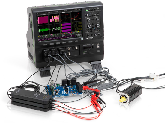
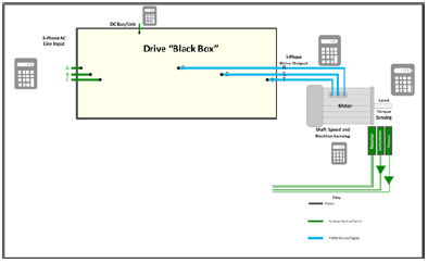
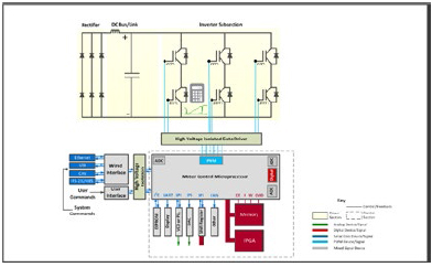
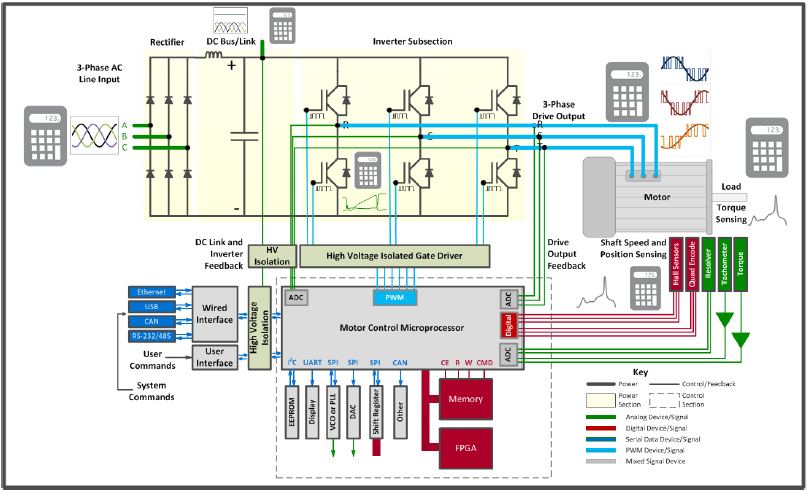
Complete Drive System Debug
The Motor Drive Analyzer acquires drive
power section, power transistor, and
embedded control system signals, and
performs three-phase power analysis
of the power section waveforms.
Correlation of drive system behaviors to
embedded control loop signals enables
debug and analysis of all aspects of the
complete motor drive. |
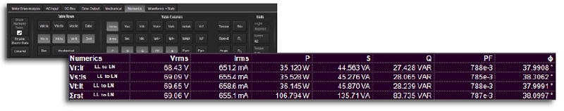
Numerics Measurement Table
Various voltage, current, power (real,
apparent, and reactive), phase angle/
power factor, and efficiency parameters
are calculated on acquired voltage and
current waveforms and displayed in a
table. The table is displayed along with
the acquisition waveforms. |
|
Zoom+Gate Dynamic Analysis
Capture long acquisitions and
Zoom+Gate with instant table value
updates and views of dynamic
three-phase power and motor drive
performance.
|
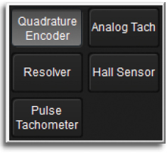
Most Complete Motor
Mechanical Integration
Simple integration is provided for
nearly any type of speed, rotation or
position sensor, including analog and
digital (pulse) tachometers, Brushless
DC (BLDC) Hall sensor, Quadrature
Encoder Interface (QEI), and Resolvers.
Additionally, Hall sensor and QEI signals
can be integrated through digital
inputs, preserving valuable analog input
channels for other signals. |
|
|
|
|
| |
| |
| |
| THE MOTOR DRIVE ANALYZER – A NEW CLASS OF INSTRUMENT |
| |
Instrument Evolution
The increasing speed, size, and complexity of three-phase power electronics and drives systems calls for new
instrument paradigms that can acquire any drive or motor signal and perform any debug, validation or analysis
on the complete drive system, including three-phase power and efficiency calculations.
That new instrument is the Teledyne LeCroy Motor Drive Analyzer. It has capabilities that previously required
multiple instruments. |
| |
The Motor Drive Analyzer has the bandwidth (1 GHz at 2.5 GS/s), inputs (8 analog channels + 16 optional digital channels), acquisition memory
(50 Mpts/ch standard, up to 250 Mpts/ch optional) to acquire any signal, from highspeed embedded control signals to low-speed mechanical
signals, and the power system signals in between. Then, |
| |
it performs three-phase and mechanical power analysis beyond what a power analyzer instrument can do. One acquisition system means one
result on one display, and faster understanding. |
| |
 |
| |
Motor Drive Analyzer Complete Capability
Power analyzers perform a single function, and have their place as a “golden-reference” power measurement device. But
they are limited to steady-state analysis and provide simple “black-box” analysis. 4 channel and/or 8-bit oscilloscopes are
good for basic embedded control debug and validation, but they lack enough inputs for complex drive system and control
loop analysis, and don’t have enough resolution to precisely measure power and efficiency values.
The Motor Drive Analyzer has none of these limitations, can acquire any analog, digital, serial data, or power signal and
perform complex three-phase power calculations and dynamic drive and control loop analysis. |
| |
| Power Analyzer Test Coverage |
4 Channel and 8-bit Oscilloscope Test Coverage |
 |
 |
|
| |
| Teledyne LeCroy Motor Drive Analyzer Test Coverage |
 |
| |
| MORE CAPABILITY THAN YOU EVER IMAGINED WAS POSSIBLE |
| |
The Motor Drive Analyzer provides an extensive range of capabilities to allow you to debug your three-phase power electronics or motor drive
design faster than ever before. Don’t limit yourself to one screen – attach a UHD (4k) monitor and create a larger palette to perform your analysis on. |
| |
 |
| |
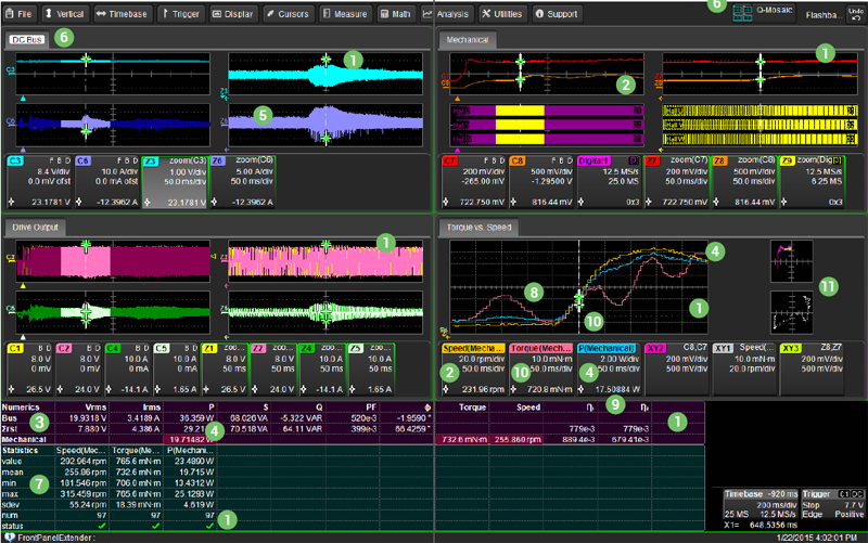
1. Zoom+Gate Mode
Take a single long acquisition of a dynamic event, and with the press of one button, zoom through the waveforms and gate the measurement results to the zoomed area.
Change the zoom position and the measurement tables and per-cycle “synthesized” Waveforms update instantly.
Gain faster understanding of dynamic drive and motor behaviors.
2. Comprehensive Speed Integration
Supports Hall sensors, Quadrature Encoder Interface (QEI) and Resolver interface for speed calculations
3. Numerics Table
User-definable and quickly summarizes the mean value for the entire acquisition
4. Touch to Learn
Simply touch a measurement and a per-cycle “synthesized” Waveforms is created showing the change in that measurement over time
5. Vertical Zooming
Capture then vertically zoom for detail, as shown here in the DC bus voltage and current signals
6. Q-Scape Displays
Use Q-Scape multi-tabbed displays to organize waveforms onto separate tabs, then view them all at once, or one tab at a time
7. Statistics Table
Displays the complete measurement set statistical data for any Numerics table measurement
8. Per-cycle “Synthesized” Waveforms
Enhances and speeds understanding of complex behaviors. Note the red trace (Torque) clearly shows torque ripple behaviors.
9. Multi-Stage Power Analysis with Efficiency
Calculated stage-stage and overall (cumulative) efficiency independently for greater understanding
10. Cursors
Place a cursor on any waveform and get an instantaneous reading of drive behavior
11. XY Displays
Up to 12 different XY displays on up to 8 different XY grids, or conventional grids |
| |
| |
| BEYOND “NUMBERS” - MORE INFORMATION |
| |
| Numerics Measurement Table |
Like a power analyzer, a user-configurable table is provided for display of a selection of power (real, apparent, reactive), power factor, phase
angle, efficiency, voltage, current or motor mechanical parameters. Up to 120 values total may be displayed in 10 rows and 12 columns for any selection of input or output individual phase or total three-phase, |
| |
DC bus/link, or motor mechanical values. Efficiency, slip, and rotor angle may also be displayed.
The numeric values displayed are mean values from a statistical data set that is calculated on a “per-cycle” basis using a user-defined
synchronization source signal. This display corresponds to what is normally provided by a dedicated power analyzer instrument. |
| |
 |
| |
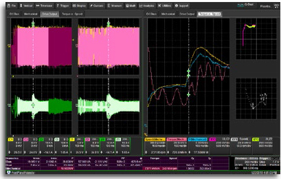 |
Per-cycle “Synthesized” Waveforms
A single averaged value “hides” dynamic behaviors. Simply
“touch” the value in the Numerics table and a detailed percycle
Waveform will be created from the complete per-cycle
measurement set and then automatically displayed timecorrelated
to the original acquisition or zoomed areas of the
acquisition. Statistical values (min, max, number, etc.) can
also be displayed. Use this advanced capability to correlate
complex drive behaviors to other control or power system
waveforms, and to debug drive system problems. This
capability is not provided in any Power Analyzer instrument. |
|
This two second capture shows the drive output waveforms on the
left and the Torque, Speed and Mechanical Power Waveform per-cycle
values over time are shown to the right. |
| |
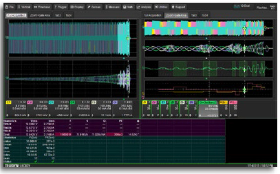 |
Zoom+Gate Mode
Enable Zoom+Gate mode to create zooms of all channel
acquisitions and gate the Numerics and Statistics measurement
tables to the zoomed area. Per-cycle displayed
Waveforms will be zoomed and time-correlated to the other
Zoomed waveforms. Change the zoom location and size
and the data will instantly update. Scroll quickly through
your measurement set to gain fast and deep insight into
drive and control system behaviors. |
|
| |
| MORE DEBUG AND VALIDATION FLEXIBILITY |
| |
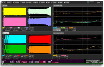
Dynamic Drive Response
The long acquisition memory in the Motor Drive Analyzers
(up to 250 Mpts/Ch) provides unique capabilities for motor
and drive dynamic response analysis. For example,
25 seconds of continuous acquisition capture is possible
at a sample rate of 10 MS/s. This permits complete understanding
of dynamic drive behaviors, such as startup,
application of load, or fast changing load conditions, and
correlation of drive response problems to control system
instructions or power section failures. |
 |
|
| |
This 480V drive has 10 second acquisitions for the AC Input and Drive
Output (on the left) and on the right are shown power, efficiency and
power factor Waveforms over time. |
|
|
Motor Mechanical Integration
The combination of 8 analog and 16 digital inputs (optional) in the Motor Drive
Analyzers provides more motor integration capability than a power analyzer
instrument. For instance, not only can standard analog and digital (pulse) tachometers
be integrated for speed sensing, but analog Resolvers, digital Quadrature Encoder
Interface and Brushless DC Hall Sensors may also be used to provide speed, direction,
and absolute position information, not normally possible with a power analyzer. |
 |
|
| |
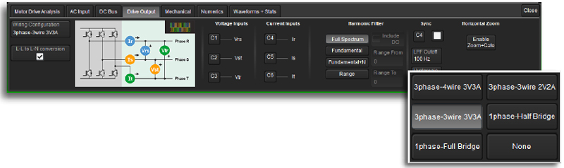
Flexible Setup Capability
The eight analog input channels provide capability for direct measurement of three voltage and three current signals from an AC Line input or Drive Output. However, support is also provided for a two-wattmeter measurement method for three-phase power, which allows three-phase measurements
to be made using two voltage and two current signals. Therefore, input/output efficiency measurements of a complete drive can be performed using the eight analog input channels. Support is also provided for a Line-Line to Line-Neutral voltage conversion so as to allow intuitive line-line probing with per-phase line-neutral reported results. |
| |
 |
| |
| |
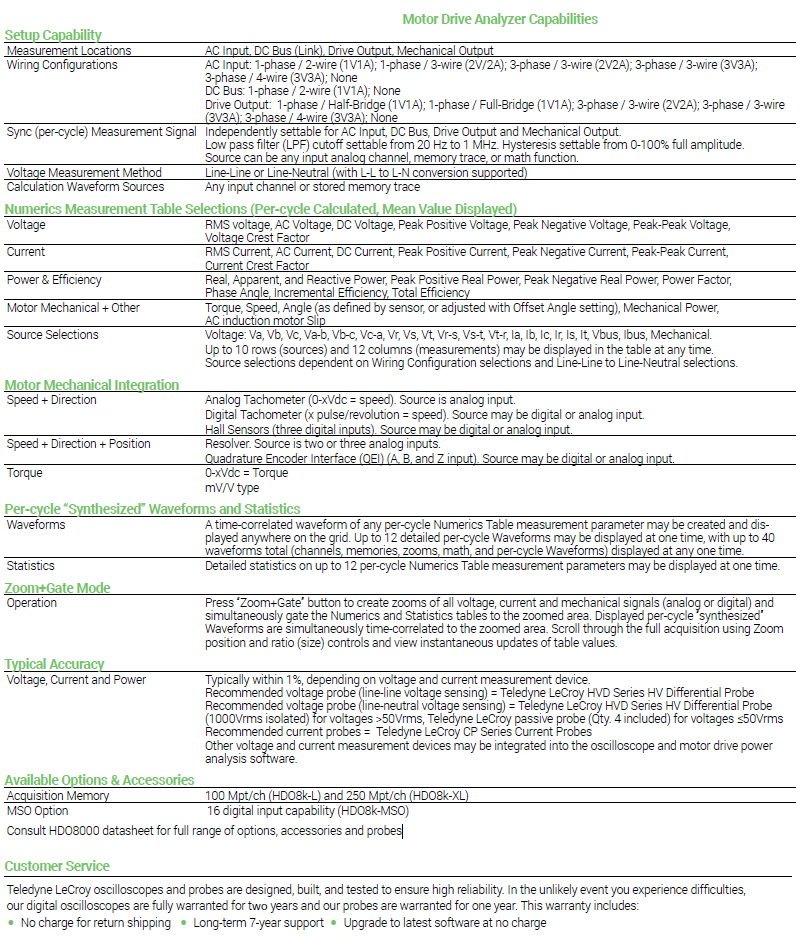
| CAPABILITIES AND PERFORMANCE |
| |
 |