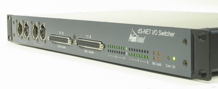
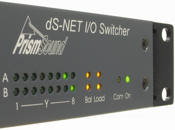
The dS-NET-I/O Switcher provides cascadable 16-into-2 relay switching, and may be used for switching either analogue or digital (AES3) audio signals . The I/O Switcher is primarily intended for use with the dScope Series III test and measurement system. It is serially-controlled using the Prism Sound dS–NET protocol.
Connections
The two 'Bus' connections are each provided on both male and female XLR connectors, allowing each to be used as either an 'input switcher' (to drive dScope's analyzer inputs from a selection of many EUT outputs) or an 'output switcher' (to drive a selection of EUT inputs from the dScope's generator outputs).
Many I/O Switchers can be cascaded together to make larger input or output switching matrices by connecting the second XLR connector to a daisy-chain of I/O Switchers. Alternatively, one of the I/O Switcher's buses can be used as an 8-into-1 input switcher and the other as a 1-into-8 output switcher.
The 16 'channel' connections are provided as two 'Groups' of eight channels, each group on a 25–way female D-sub connector. Breakout cables to XLRs (male for output switching and female for input switching) are available from Prism Sound, alternatively the operator can construct his own cable to suit the EUT. This configuration allows the I/O Switcher to serve as both input and output switcher without modification, since there is no need to fit differently-sexed channel XLRs. |
| |
Architecture
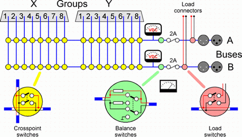
The crosspoint switching is organised with two Buses ('A' and 'B') and two eight-channel Groups ('X' and 'Y'). Together these form a 16x2 switching matrix. All inputs and outputs are two-leg balanced connections, although the –ve (cold) legs can be jumpered to signal ground for unbalanced operation if required. The crosspoint relays can carry a maximum current of 2A, and switch a maximum voltage of 250V. Note that repeated switching at high currents is likely to damage the relay contacts. |
| |
Additional features
|
As well as providing the basic 16-into-2 switching matrix, the I/O Switcher has three additional functions:
|
| Balance-test mode |
each Bus can be switched into 'balance-test' mode, a special mode used in the input switching configuration, for measuring the output balance of the EUT. In this mode, the Bus output is taken between signal ground and the centre tap of a 600R resistor connected between the two legs of the selected input. The resistor is composed of two 0.01% matched halves in order that the balance of the resistors is unlikely to dominate the output balance of the equipment under test. The dScope's analyzer input impedance should be set to 600R in order to enact the standard method of balance measurement. A maximum signal amplitude of 28dBu (19.45Vrms) can be tolerated by the balance-test circuit; beyond this, the resistors may be damaged. |
| |
Load switching
|
each bus can be connected to a load applied to a pair of 4mm sockets on the rear of the I/O Switcher. This is useful for power amplifier testing. The maximum load current is 12A if the switcher is only connecting the load to the XLR connector of the Bus, i.e. if the load current does not flow through the switching matrix. If the load is applied to a Group channel via the switching matrix, the maximum matrix current of 2A must not be exceeded. A fuse is included to protect the switching matrix from excessive currents. |
| |
| DC measurement |
he DC voltage on each leg of each bus can be read, in 1V steps, over the range+/-128V. This is primarily intended for checking phantom power sourcing from inputs under test. |
| |
| Serial control |
The I/O Switcher's serial control port follows the dS–NET standard, based on the RS–232 protocol. Up to 64 dS–NET devices can be daisy-chained from the dScope's dS–NET connector using special dS–NET cables. dS–NET devices are differentiated by setting different addresses for each on rear-panel DIP switches. dS–NET devices are easily controlled from the dScope's VBScripting system at a high level.
In the case of the I/O Switcher, no complex binary manipulations or sequences are required; the desired channels can be simply selected in a single operation. If multiple switchers are connected to form large arrays, these can be described at the head of the script, allowing the whole array to be addressed as if it were a single switcher. Details of how to control the I/O Switcher from a VBScript can be found in the dS-NET peripherals section of the Scripting Manual. |