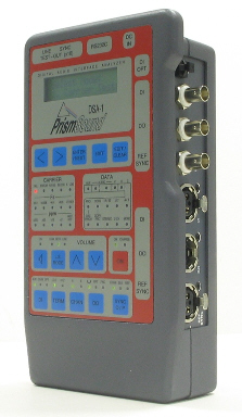
The DSA-1 is an invaluable trouble-shooting tool for digital audio equipment and installations. It is unique as a hand-portable, battery-powered instrument for electrical, timing and data analysis of digital audio signals; these factors are vital in establishing reliable interconnection operating margins.
The DSA-1 has become the standard tool for digital audio installation in broadcast and recording studios throughout the world.
The latest version 2.20 software features a versatile signal generator, plus a host of extended analysis and logging functions. DSA-1 software upgrades are easily user-installed by a simple serial-download to flash memory.
The facilities of the DSA-1 are summarised below:
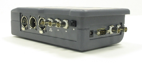
- XLR, coaxial (BNC or RCA) or optical test input formats are supported. XLR and coaxial test outputs allow for loop-through testing (with switchable termination impedance), de-jittering, Channel Status editing, signal generation and carrier format conversion.
XLR and coaxial reference inputs are provided for connection of an AES11 or Wordclock reference sync. The sync is used for optionally calibrating sample-rate measurements, measuring relative carrier phase, and providing external reference capability for the signal generator functions.
- Front-panel LEDs indicate:
- Carrier failure
- Biphase or parity violation
- 'Near Fail' - eye-width less than 50%
- Block error - block length NOT 192 samples (phase error if DSA-1 output is in function generator mode)
- 'Analogue' - sub-20kHz signal detected
- Base sample rate - 32kHz, 44.056kHz, 44.1kHz, 48kHz or 'other'
- Sample rate accuracy - ±2ppm, ±10ppm, ±50ppm, ±200ppm
- Detected audio word-length 16, 20 or 24 bits
- Validity flag
- User-bit activity
- Basic Channel Status:
- Professional / consumer
- Emphasis
- SCMS / copy status
- Channel mode: stereo / 2-channel / mono
- CRC error
- A<>B (A and B Channel Status different)
- A monitoring D-A converter is included, with headphone jack, plus built- in loudspeaker and volume control.
- Oscilloscope connections: To aid display of carrier waveform, the DSA- 1 provides an isolated, unbalanced feed of the test-signal, plus trigger pulse, on a pair of BNC connectors. The trigger point can be selected from test-signal's A-channel preamble, B-channel preamble, block-start preamble or can be derived from the reference sync input. |
- The following Input Analysis functions are provided:
- Sample-rate display - in Hz and ppm; internal TCXO is accurate to ±3ppm over temperature and lifetime (±0.5ppm to special order); software calibration to external reference can be 'learned' in non-volatile memory for ±1ppm performance over several weeks.
- Interface Jitter measurement is presented in three different forms: 'fs Jitter' measures jitter attributable to sourcing equipment, 'Data Jitter' measures the total from source and cabling (which may be program-dependent), and 'Eye- narrowing' measures cable effects in a way which is independent of program content, either at the recommended 200mV p-p amplitude or at zero crossings. To assess low-frequency jitter content the corner frequency of the DSA-1's reference PLL can be set to either 700Hz or 1.5kHz.
- Carrier amplitude is displayed in volts or millivolts p-p.
- A biphase / parity error count is maintained continuously, and is examined and cleared through a menu.
- The phase of the Test Input carrier versus the reference sync is displayed in % and degrees.
- For a balanced Test Input, common-mode carrier amplitude is measured, and can be used to detect wiring faults and poor cabling.
- The low-band amplitude measurement shows the sub-20kHz amplitude measured at the Test Input; this can be used to detect hum or analogue audio.
- The audio amplitude of the Test Input is displayed as a bargraph meter, and also in dBFS. The display can be single channel or stereo and both peak hold and overload indications are also provided. A hexadecimal display mode is provided for engineering applications.
- Bit activity is indicated for the incoming audio word - each bit is shown as low or active (high or changing).
- Incoming Channel Status is split into fields according to the professional or consumer state of the signal. For each field, binary data is displayed along with a description of the meaning of the data. Every Channel Status field can be examined in this way, including timecode, alphanumeric labels, emphasis flags, and SCMS / copy protection. Simple binary display of the Channel Status bytes is also possible.
- Measurement results can be dumped to the DSA-1 Results Log or printed directly if a serial printer is connected.
- Signal generator/ editor: this is available as a 'function' at the Test Output and has two modes:
- Generator 1, providing greatest a range of common functions
- Generator 2, providing special generator functions for use in jitter testing and bit-error detection which operate in conjunction with the DSA-1 jitter measurement and Channel Checking functions
The generator sync source may be selected as the reference sync input (AES11 XLR or coax, or Wordclock at any sampling frequency between 30KHz and 50KHz ), or internal at 44.1KHz or 48KHz.
Generator functions include:
- Sine
- Square
- Triangle
- Ramp
- PRS: a pseudo-random sequence (white noise), also used for integrity testing
- Pulse: one or more samples of programmable amplitude, with polarity control, separated by zeros - useful for testing digital metering systems
- J-test: a proprietary Prism Sound test signal for investigating cable-related jitter problems
Amplitude, frequency and word-length may all be adjusted where applicable.
The generator Channel Status can be formed with total flexibility; all fields (professional or consumer) may be specified; this also applies to the Validity flag.
In in-line edit mode, the analyzer Test Input (DI) is selected as the generator sync source. The audio, valid bit and Channel Status bit data fields on the AES format can be individually modified or passed through, so the user can choose to impose an audio signal (or mute the audio) if needed, or to patch the state of the 'valid' bit or the Channel Status - in any combination.
When Generator 2 is selected, jitter may be added to the generator output; the modulation function may be wide-band pseudo- random (PRS), band-limited PRS, low-frequency (fs/8), or cable simulation (a cell-length dependent jitter which simulates the Data Jitter of a long or poor quality cable). The amplitude of the jitter modulation is variable.
In in-line edit mode, jitter can also be added to incoming signals so that links can be degraded to test operating margin.
Generator settings can be logged so that analyzer results and generator settings can be uploaded together for a particular test or incident report.
- The Channel Check feature tests the integrity of a data channel. This feature is useful where occasional data errors or link drop-outs occur or if the transmission medium is particularly poor (such as a long cable run). Applications also include testing recording equipment or transmission and routing systems, ranging from a point-to-point cable to a satellite link.
Channel Check mode uses the Generator 2 signal generator PRS function (pseudo-random noise). The same versatile sync-source selections are available as for the main signal generator.
The transmission bit-error check allows long-term monitoring of every incoming sample against the generated PRS (sequence). The word-length for the check is variable, and a log of failures is kept against time. Tests can be performed on A or B or both channels together. Although the DSA-1 can generate and test simultaneously, the transmitter and checker can be separate units. Path delay does not affect this test mode, allowing record/replay or long-haul links to be tested.
The Test Output can have jitter added (see above) if desired which can be useful to establish the operating margin if, for example, a long run of cable is used.
- The DSA-1 Watchdog feature allows continuous monitoring of key parameters over a period of time. This provides a solution in situations where a fault occurs intermittently and infrequently by logging errors or violations over a period of time.
Log entries will be made with a time stamp (from start of test). All 'Carrier' and 'Data' front-panel LED indicators can be individually selected for monitoring; typical configurations might include the 'FAIL' and 'NEAR FAIL' indicators, 'VALID' and the Channel Status 'CRC ERROR' indicator.
- The DSA-1 Microscope feature allows in-line gain (0 to +90dB) to be applied to the Test Input signal. The DSA-1's D-A converter and the 'function' digital output monitor the post-gain signal. This allows, for example, small-signal performance and dither or noise-shaping algorithms to be evaluated. Input wordlength can be set to verify the correctness of dither schemes or simply so that spurious low-order bit-activity is ignored. Overload indicators are included.
- The Automatic Test Sequence facility provides both sophisticated and rapid GO / NO-GO testing which can easily be used in the field by non- specialist operators. It allows any of a wide range of DSA-1 measurements to be applied quickly, and in a pre-arranged sequence, against user-programmable test limits.
Test Sequences are programmed into the DSA-1 and the operator need only select the desired Sequence and run it. Results can optionally be stored in the log or printed.
Four pre-programmed Test Sequences are provided which cannot be modified; a further four Test Sequences, downloaded via the serial port, may be stored in the instrument to provide a selection of 'house' benchmarks or test standards.
The four built-in Test Sequences are:
- Global
- Professional (AES3)
- Consumer (IEC958)
- Strict Professional (Prism Sound recommendation)
These Sequences test the parameters of the signal against the relevant specification and report any inconsistencies.
User-defined Test Sequences are written and compiled (see below) from a simple programming language, on the user's PC, and loaded into the DSA-1's non-volatile memory via RS232 using the DSA-1 Manager software.. This allows technicians to apply house test standards at the touch of a key.
- The Results Log section provides a range of log management facilities. Most measured parameters, including Carrier measurements, Test Sequence results, Channel Status snapshots and the results of Channel Checking or Watchdog operation can be printed immediately via RS232, or retained in the log (non-volatile memory). The contents of the log may later be inspected, printed or uploaded to the user's PC, from where they can in turn be printed, edited or incorporated into reports.
The main measurement menus such as Carrier Tests, Data Tests, Test Sequences and Generator setup have a 'log' menu item which dumps all readings or settings for the section to the log or printer.
Channel Checking and Watchdog modes automatically pass their results to the log or printer.
Facilities are provided for marking blocks of test results with a series of 'block markers' in the log and for viewing and clearing the log.
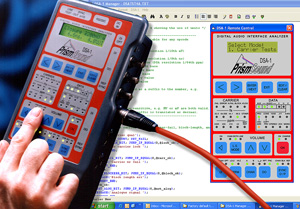
- DSA-1 Manager software suite:
The DSA-1 is supplied with "DSA-1 Manager software" which allows the DSA-1 to be used with a Windows PC. This combines several functions including:
- Download of firmware updates
- Uploading of test results logged by the instrument
- Editing, compiling and downloading of customized Go/No-go Test Sequences
- Real-time remote control from the host PC with "virtual DSA-1" GUI
The DSA-1 manager software runs on almost any PC running Windows 95, 98, 2000 or XP. The PC must have a serial (COM) port available for connection to the DSA-1. Alternatively, as USB port (1.0 or higher) can be used with the USB-COM port adapter supplied with the DSA-1. The DSA-1 can also be controlled over a network connection or over the internet using third party virtual serial port software.
Note for existing DSA-1 owners:
DSA-1 software updates and the DSA-1 Manager software are available for download from the downloads page.
|