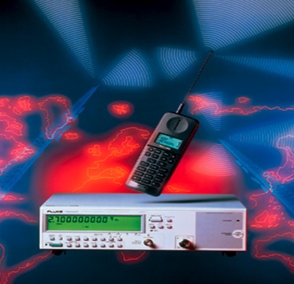
(주)티앤씨

본문 바로가기


거리측정기
멀티미터
범용 계측기
스코프 미터
시간 및 주파수 교정기
     
실내 공기 측정기
압력분야 교정기
열화상 카메라
온도미터
온도분야 교정기
       
전기분야 교정기
전기 측정 측정기
전력 분석기
절연저항 측정기
접지저항 측정기
       
클램프미터(후크미터)
프로세스 캘리브레이터
Accessary


주파수 표준기 타임 & 주파수 카운터
 
Fluke 164 휴대용 다기능 카운터
PM6681 타이머 & 카운터
PM6681R 루비듐 카운터
PM6685 주파수 카운터
PM6685R 루비듐 주파수 카운터
PM6685R 루비듐 주파수 카운터
PM6685R 루비듐 주파수 카운터
 
PM6685 주파수 카운터
 

PM6685 주파수 카운터


상기 장비는 주파수 카운터로서 , 사용하기 쉬운 경제적인장비이며, 
높은 정밀도에서의 측정으로 연구소 나 개발용으로  많이 쓰이고 
있습니다.


1. 주파수 A : 0.1 Hz to 160MHz
2. 주파수 B : 0.1 Hz to 16MHz
2. 주파수 C : 70 MHz to 1.3GHz(RF적용)
3. 주파수 분해능 : 7 Digit/s
4. 측정 모드 : 주파수A,B ,펄스폭, 주기 , 듀티사이클, 하강/상승
시간, RPM , 시간격
5. Warm Up Time : 30 분
6. Battery Operating Time : 2 시간
7. 외부기준 입력 : 10 MHz

 
Measurement Functions
  Frequency, Burst Frequency, Period, Ratio f1/f2, Pulse Width, Duty Factor, Totalize A
Frequency A, C
Input A: 10 Hz to 300 MHz
Input C (Optional Input Pre-Scaler): PM9621: 70 MHz to 1.3 GHz
  PM9624: 100 MHz to 3.0 GHz
  PM9638: 300 MHz to 8.0 GHz
Resolution: 10 digits/s measurement time
Burst Frequency A
Frequency range: 100 Hz to 80 MHz
PRF range: up to 1 MHz
Burst duration: 0.5 μ to 1.5 s,min. 3 cycles in burst
Burst Frequency C
Frequency range: 100 MHz to 8GHz
PRF range: up to 1 MHz
Burst duration: 0.5 μs to 1.5 s
Period A
Range: 3.3 ns to 100 ms
Resolution: 10 digits/s measurement time
Ratio A/E, C/A
Range: 10-9 to 109
Frequency range: Input A: 10 Hz to 300 MHz (prescaling factor 4)
  Input E: 10 Hz to 80 MHz
  Input C: See input C frequency range
Pulse Width A
Range: 6 ns to 10ms
Frequency range: 50 Hz to 60 MHz
Voltage range: 100 mV p-p to 70 V p-p
Duty Factor A
Range: 0 to 1
Frequency range: 50 Hz to 60 MHz
Voltage range: 100 mV p-p to 70 V p-p
Totalize A
  Event Counting on A with manual start and stop
Range: 0 to 1014
Frequency Range: 0 to 100 MHz


Optional TimeBase
Standard: PM6685/-1- (Non -Retrofit)
Calibration adjustment tolerance* * * at +23ºC ± 3ºC: < 1 x 10⁻⁶
Uncertainty due to:  
Aging /24 hr: N/A*
Aging /month: < 5 x 10⁻⁷
Aging /year: < 5 x 10⁻⁶
Temperature Stability (reference temp at +23ºC): 0-50ºC: < 1 x 10⁻⁵
  20ºC -26ºC: 3 x 10⁻⁶
Line voltage variation of ±10%: < 1 x 10⁻⁸
Power On Stability: Not Specified
Total Uncertainty* * * * at 2σ (95%) confidence  
interval and at 23ºC ± 3ºC: After 1 Year Cal interval < 7 x 10⁻⁶
  After 2 Year Cal interval < 1.2 x 10⁻⁵
Total Uncertainty* * * * at 2σ (95%) confidence  
interval and at 0-50ºC: After 1 Year Cal interval < 1.2 x 10⁻⁵
  After 2 Year Cal interval < 1.5 x 10⁻⁵
OCXO: PM6685/-5- (PM9691)
Calibration adjustment tolerance* * * at +23ºC ± 3ºC: < 2 x 10⁻⁸
Uncertainty due to:  
Aging /24 hr: < 5 x 10⁻¹⁰* *
Aging /month: < 1 x 10⁻⁸
Aging /year: < 7.5 x 10⁻⁸
Temperature Stability (reference temp at +23ºC): 0-50ºC: < 5 x 10⁻⁹
  20ºC -26ºC < 6 x 10⁻¹⁰(typical values)
Line Voltage variation of ±10%: < 5 x 10⁻¹⁰
Power-on stability: 1 x 10⁻⁷ Deviation versus final value
  after 24 hr on time, after a warm-up time of: 15 min
Total Uncertainty* * * * at 2σ (95%) confidence  
interval and at 23ºC ± 3ºC: After 1 Year Cal interval: < 9 x 10⁻⁸
  After 2 Year Cal interval: < 1.5 x 10⁻⁷
Total Uncertainty* * * * at 2σ (95%) confidence  
interval and at 0-50ºC: After 1 Year Cal interval: < 1 x 10⁻⁸
  After 2 Year Cal interval: < 2 x 10⁻⁷
OCXO: PM6685/-6- (PM9692)
Calibration adjustment tolerance* * * at +23ºC ± 3ºC: < 5 x 10⁻⁹
Uncertainty due to:  
Aging /24 hr: < 1 x 10⁻¹⁰* *
Aging /month: < 3 x 10⁻⁹
Aging /year: < 2 x 10⁻⁸
Temperature Stability (reference temp at +23ºC): 0-50ºC: < 2.5 x 10⁻⁹
  20ºC -26ºC: < 4 x 10⁻¹⁰(typical values)
Line Voltage variation of ±10%: < 5 x 10⁻¹⁰
Short term stability: (root Allan Variance)
  T = 1 s: 5 x 10-11
  T = 10 s: 5 x 10-12
Power-on stability: 5 x 10⁻⁹ Deviation versus final value
  after 24 hr on time, after a warm-up time of: 10 min
Total Uncertainty* * * * at 2σ (95%) confidence  
interval and at 23ºC ± 3ºC: After 1 Year Cal interval: < 2.5 x 10⁻⁸
  After 2 Year Cal interval: < 5 x 10⁻⁸
Total Uncertainty* * * * at 2σ (95%) confidence  
interval and at 0-50ºC: After 1 Year Cal interval: < 2.5 x 10⁻⁸
  After 2 Year Cal interval: < 5 x 10⁻⁸

* N/A: Not discernible, neglectable versus 1°C temperature variation. * * After 14 days continuous operation * * * Calibration Adjustment Tolerance: Is the maximal tolerated deviation from the true 10MHz frequency after a calibration. When the reference frequency does not exceed the tolerance limits at the moment of calibration, an adjustment is not needed. * * * * Total uncertainty: Is the total possible deviation from the true 10MHz value under influence of frequency drift due to aging and ambient temperature variations versus the reference temperature. The operating temperature range and the calibration interval are part of this specification.

Input and Output Specifications
Input A
Frequency Range: 10 Hz to 300 MHz
Coupling: AC
Impedance: 1 MΩ//25pF or 50Ω, VSWR< 2:1
Sensitivity (SineWave): 10 mV rms, 10 Hz to 50 MHz
  15 mV, 50 MHz to 100 MHz
  20 mV, 100 MHz to 150 MHz
  30 mV, 150 MHz to 200 MHz
  50 mV, 200 MHz to 300 MHz
Pulse: 50 mV p-p, 3 ns minimum pulse width
Dynamic Range: 30 mV p-p to 70V p-p
Manual Trigger
Sensitivity Range:  
  10 mV rms to 10 Vrms, variable in 3 dB steps, indicated on bar graph
Trigger Level: Selectable for optimum triggering on
  waveforms with duty factors of <0.25, 0.25 to 0.75 and
  >0.75
Trigger Slope: Positive or Negative
Auto Trigger
  Automatic setting of input signal conditioning circuits for
  optimum triggering on different amplitudes and
  waveforms
Frequency: Minimum 50 Hz
Sensitivity Range: 10 mV rms to 25V rms
Signal Monitor
  A bar graph displays actual input signal level in 3 dB
  steps, 10 mV rms to 10 Vrms
Low Pass Filter
  100 kHz nominal 3 dB point
  Minimum 40 dB attenuation at 1 MHz
Damage Level
1 MΩ Impedance: 350V (DC + AC peak) at DC to 440 Hz, falling to 12 Vrms
  at 1 MHz and above
50 Ω Impedance: 12 V rms


Auxiliary Functions
External Arming/External Gate
  External signal on input E can be used to inhibit start
  and/or stop triggering
  Stop arming is not applicable to Pulse Width and Duty
  Factor measuring modes
Start Arming Delay
  OFF or 200 ns to 5s in 100 ns steps
Nulling/Frequency Offset
  Nulling enables measurements to be displayed relative to
  a previously measured value or any value entered in via
  front panel keys


Optional Pre-Scalers
Input C (PM 9621)
Frequency Range: 70 MHz to 1.3 GHz
Pre-Scaler Factor: 512
Sensitivity: 10 mV rms to 12V rms, 70 to 900 MHz
  15 mV rms to 12V rms, 900 to 1100 MHz
  40 mV rms to 12V rms, 1100 to 1300 MHz
Amplitude Modulation: Dc to 0.1 MHz: Up to 94% depth
  0.1 to 6 MHz: Up to 85% depth
  Minimum signal must exceed Input Sensitivity
Impedance: 50Ω nominal, ac coupled, VSWR < 2:1
Damage Level: 12V rms pin diode protected
Connector: BNC
Input C (PM 9624)
Frequency Range: 100 MHz to 3.0 GHz
Pre-Scaler Factor: 64
Sensitivity: 20 mV rms to 12V rms, 100 to 300 MHz
  10 mV rms to 12V rms, 0.3 GHz to 2.5 GHz
  20 mV rms to 12V rms, 2.5 GHz to 2.7 GHz
  100 mV rms to 12V rms, 2.7 GHz to 3.0 GHz
Amplitude Modulation: DC to 0.1 MHz: Up to 94% depth
  0.1 to 6 MHz: Up to 85% depth
  Minimum signal must exceed Input Sensitivity
Impedance: 50Ω nominal, ac coupled, VSWR < 2.5:1
Damage Level: 12V rms pin diode protected
Connector: Type N Female
Input C (PM9638)
Frequency Range: 3 MHz to 8 MHz
Prescalar Factor: 256
Operating Input Voltage Range: 300...500 MHz: -21...+30 dBm
  0.5...3 GHz: -27...+30 dBm
  3.0...4.5 GHz: -21...+30 dBm
  4.5...6.0 GHz: -15...+30 dBm
  6.0...8.0 GHz: -9...+30 dBm
Impedance: 500 Ω nominal, AC coupled, VSWR <2:1
Max Input Voltage Without Damage: 7 V RMS, pin diode protected
Damage Connector: Type N female


External Reference
Input D
  The use of external reference is indicated on the front
  panel display
Input Frequency: 10 MHz
  with optional reference multiplier PM 9697
Voltage Range: 200 mV rms to 10V rms
Impedance: Approximately 1 kΩ, ac coupled
Input E
  Used in ratio A/E and external arming / gating modes
Frequency Range: DC to 80 MHz
Pulse Width: 6 ns minimum
Slew Rate: 2V/μs minimum
Trigger Level: TTL level, 1.4 V nominal
Trigger Slope: Positive or Negative
Impedance: Approximately 2 kΩ, dc coupled
Damage Level: ±25V peak
Reference Output G
Frequency: 10 MHz, Sine Wave
Output: >0.5 V rms into 50Ω load, >0.7 V rms into hi
  impedance load, Ac coupled


Options (Battery Unit PM 9623)
Battery Unit (Option PM 9623)
  The PM 9623 is a rechargeable battery unit for mounting
  inside the counter
Battery Type
  Sealed lead-acid cells
Battery Capacity
  at 25ºC
Standby Mode: Typically 20 hours with Oven Time Base
Operating Mode:  
  Typically 3 hours without options, 2.5
  hours with Oven Time Base, and 2 hours with Oven Time Base and Input C
Recharge Time
  Typically 8 hours in standby mode
Battery Protection: Overcharge and deep discharge protection
External DC: 12V to 24V via socket on rear panel (16V
  to 24V to charge internal battery)
Line Failure Protection: Counter automatically switches
  to internal battery or external DC when the line voltage falls below 90V AC
Temperature
Operating: 0ºC to +40ºC
Storage: -40ºC to +50ºC


회사소개 제품소개 견적및데모요청

법인명 : 주식회사 티앤씨  경기도 광명시 하안로 60, 광명SK테크노파크 A동 808호  사업자등록번호 108-81-96584  대표이사 : 김용정
  전화: 02-2635-6859   팩스: 02-6008-3672   이메일: info@tandc.co.kr

COPYRIGHT(C) 2014 TNC.ALLRIGHT RESERVED.

상단으로