(주)티앤씨
본문 바로가기
메인메뉴
회사소개
TNC 소개
위치 / 연락처
제품소개
KEYCOM
Lecroy
KEYSIGHT
Fluke
Keithley
Kikusui
Tektronix(Video)
Audio/VOIP
서비스 & 지원
견적 및 데모요청
고객센터
Q&A
자료실
사용후기
공지사항
거리측정기
멀티미터
범용 계측기
스코프 미터
시간 및 주파수 교정기
실내 공기 측정기
압력분야 교정기
열화상 카메라
온도미터
온도분야 교정기
전기분야 교정기
전기 측정 측정기
전력 분석기
절연저항 측정기
접지저항 측정기
클램프미터(후크미터)
프로세스 캘리브레이터
Accessary
데이터 로거
함수 발생기
RCL 미터
Fluke-271
Fluke-280 Series
Fluke-290 Series
Fluke-396/397
Fluke-80/81
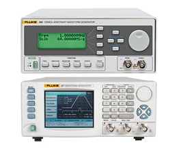
Fluke-80/81
FLUKE-80/81
Standard Waveforms
Standard Waveforms
Sine, triangle, square, positive and negative pulses, and (Model 80 only) dc
Frequency
Range
10 mHz to 50 MHz
Resolution
4 digits
Accuracy (Continuous Mode)
10 mHz to 999.9 mHz:
± 3%
1 Hz to 50 MHz:
± 0.1%
Jitter:
=0.1% ± 50 ps
Waveform Quality
Harmonic Distortion (Sine)
100 mHz to 1 MHz:
< 1% THD
1 MHz to 5 MHz:
Max harmonic < -40 dB
5 MHz to 50 MHz:
Max harmonic < -21 dB
Flatness
10 mHz to 999.9 kHz:
± 1%
1 MHz to 9.999 MHz:
± 2% ± 2%
10 MHz to 50 MHz:
-15%
Triangle and Ramp Linearity
£5 MHz (10% to 90% of Amplitude): > 99%
Square Rise/Fall Time
(10% to 90% of Amplitude): < 6 ns
Square Aberrations
< 5%
Pulse & Ramp (Model 81 Only)
Pulse Modes
Symmetrical pulse, positive pulse, negative pulse, and the complement to all pulse waveforms
Pulse Period
Range:
20 ns to 99.99s
Resolution:
4 digits
Accuracy and Jitter:
As for frequency
Pulse Width
Range:
10 ns to 999 ms
Setting Accuracy:
10 ns to 99.9ns: ± (5% + 2 ns)
100 ns to 999 ms: 3% ± (4% + 2 ns)
Resolution:
3 digits
Duty Cycle Range:
1% to 80%. Up to 99% using the complement mode 0 to 5V ± 20% produces > 10% pulse width change from pulse width setting
PWM Range:
dc to 70 kHz
Ramp Modes:
Positive or negative going ramp
Ramp Period
Range:
7 µs to 99.99s
Resolution:
4 digits
Ramp Width
Range:
5 µs to 999 ms
Setting Accuracy (5µs to 999ms):
3%
Resolution:
3 digits
Duty Cycle Range:
1% to 80%
Transition Times
Range:
8 ns to 99.9 ms in six overlapping ranges. Leading and trailing edges are independently programmable
Max Ratio between Ranges:
100 to 1
Accuracy:
8 ns to 99 ns: ± (5% + 2 ns)
Modulation
AM and SCM
External 0 to 10V produces 0 to 200%
Range:
0 to 200%, reduced to 70% at 1 MHz
Bandwidth:
dc to 50 kHz
VCO
Range:
4.7V change produces approx 1000:1 frequency change
Bandwidth:
dc to 50 kHz
FM (Model 80 only)
Range:
0 to 0.5V change produces 1% deviation
Bandwidth:
dc to 50 kHz
Amplitude
Range
Into 501/2:
10 mV to 16 Vp-p
Into Open Circuit:
20 mV to 32 Vp-p
Resolution:
3 digits
Accuracy (at 1 kHz):
± 4 % reading
DC Offset
DC Offset
Offset and amplitude are independently adjustable within two windows:
-800 mV to +800 mV
-8V to +8V
Range
± 800 mV Window:
± 795 mV
± 8V Window:
± 7.95V
Resolution
3 digits
Accuracy (At 1 kHz)
± 800 mV Window
± (1% of setting + 1% of amplitude + 0.2 mV)
± 8V Window:
± (1% of setting + 1% of amplitude + 2 mV)
Main Output
Modes
Normal (on) or disabled (off)
Impedance
50Ω ± 1%
Output Protection
Protected against continuous short to chassis ground
Sync Output
Level (Into 50Ω)
0 to 1V
Rise/Fall Time
< 3 ns
Operating Modes
Operating Modes
Continuous, triggered, phaselock, start phase, and (Model 80 only) sweep
Sweep Operation (80 Only)
Modes
Sweep may be continuous or triggered by any trigger mode
Sweep Spacing
Linear and logarithmic
Sweep Directions
Up, down, up-down, and down-up
Sweep Range
Log:
10 decades max
Linear:
3 decades max
Sweep Rate
Log:
10 ms to 999s per decade
Linear:
10 ms to 999s
Sweep Out
0 to 5V ramp proportional to frequency at rear panel BNC
Marker Output:
Output signals when marker frequency is reached
Triggered Operation
Modes
Single shot, gated, and burst
Sources
Manual (front panel key), internal trigger rate generator, and external signal input
Triggered
For each trigger, one output cycle is generated
Gated
Continuous waveform cycles are generated for the duration of the active portion of the trigger signal. Last cycle is always completed
Burst
Preset number of waveform cycles are generated by a trigger: 1 to 4,000
Manual Trigger
Key provides trigger signal
Internal Trigger Rate Generator
1 mHz to 50 kHz
External Input
Via Trig Input BNC
Impedance:
10 kΩ ± 5%
Sensitivity:
500 mVp-p
Max Input Voltage
± 20V
Min Pulse Width
20 ns
Max Frequency:
50 MHz
Slope
Positive or negative going leading edges
Trigger Level:
Variable -10V to +10V
Start Phase of Triggered Waveform
To 500 kHz:
Adjustable from -90º to +90º.
From 500.1 kHz to 50 MHz:
Adjustable range proportionally reduced as frequency increases
Accuracy (to 500 kHz):
± 3º
Phaselock Operation
Phaselock Operation
Output waveform locks to frequency and phase of external signal. Phase may be offset.
Impedance
10 kΩ ± 5%
Min Pulse Width
10ns
Locking Range
10 Hz to 60 MHz
Phase Offset (10 Hz to 19.99 MHz)
Continuously adjustable from -180º to +180º
Resolution
1º
Accuracy (1O Hz to 100 kHz)
3º + 3% of reading
General Specifications
Remote Operation
GPIB interface is standard on Models 80 and 81. HP8116A emulation mode (Model 81 only)
Environment
Operating Temperature:
0º to 50ºC, ambient
For Specified Accuracy:
Within ± 5ºC and 24 hours of last internal calibration
Storage Temperature:
-40º to +70ºC
Humidity:
80% R.H.
Power
115/230 Vac, optional 100V, 50 or 60 Hz, 60 W max
Stored Set-ups
Complete sets of front-panel set-ups stored: 30
Size
8.9 cm (3.5 in) high x 21.1 cm (8.3 in) wide x 39.1 cm (15.4 in) deep
Rack Mount Dimensions
Single:
8.9 cm (3.5 in.) H x 48.3 cm (19 in.) W
Dual:
13.3 cm (5.25 in) H x 48.3 cm (19 in) W
Weight
6 kg (12 lb)
회사소개
제품소개
견적및데모요청
법인명 : 주식회사 티앤씨 경기도 광명시 하안로 60, 광명SK테크노파크 A동 808호 사업자등록번호 108-81-96584 대표이사 : 김용정
전화: 02-2635-6859 팩스: 02-6008-3672 이메일: info@tandc.co.kr
COPYRIGHT(C) 2014 TNC.ALLRIGHT RESERVED.
상단으로